LEVEL CROSSING GATES laser cut kit OO gauge 1:76 scale Ancorton Models OOLC1
Pay in 3 interest-free payments of ... with

LEVEL CROSSING GATES laser cut kit OO gauge 1:76 scale Ancorton Models OOLC1 is backordered and will ship as soon as it is back in stock.
Couldn't load pickup availability
Description
Description
OOLC1 - Level Crossing
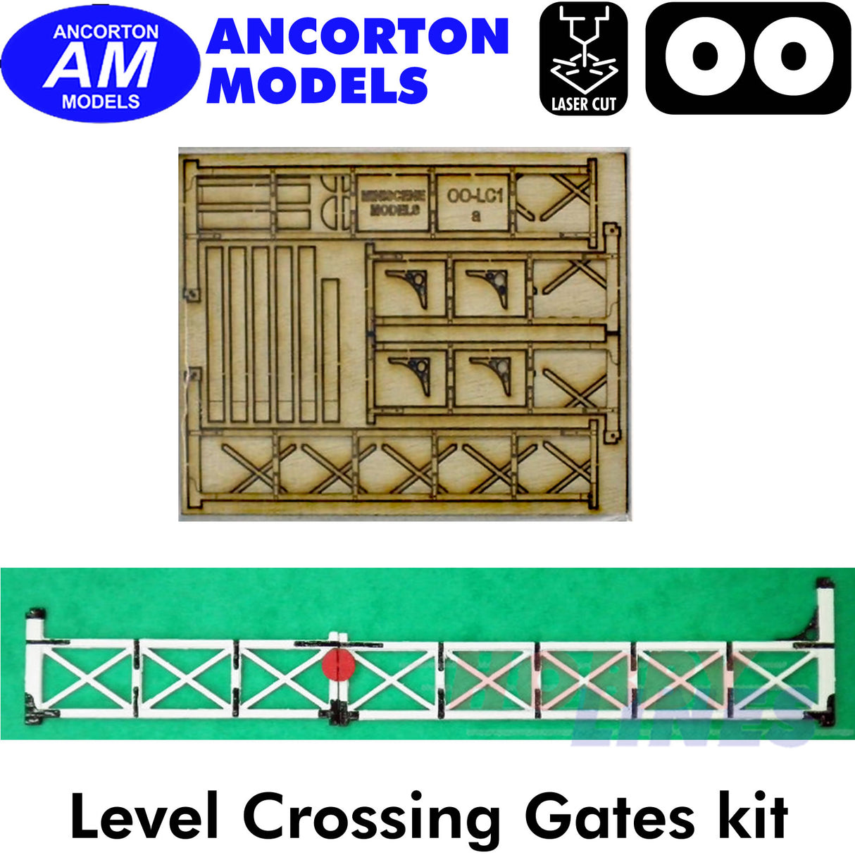
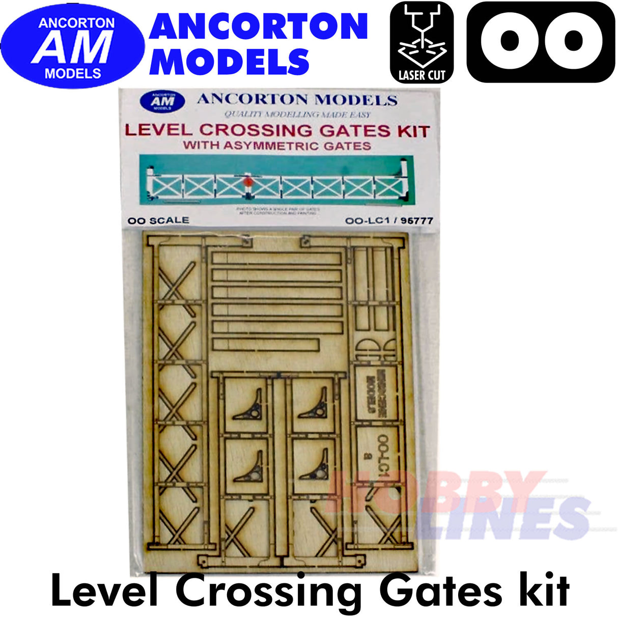
This kit contains laser cut scale wooden parts that assemble into a model of a beautifully detailed set of asymmetric level crossing gates (two pairs of gates). Assembly instructions are included.
OO Scale - Lineside items, laser cut kits
Dimensions: 3.5 mm (w) x 18.5 cm (l) x 17 mm (h)
Assembly Instructions
- Using a sharp modelling knife, carefully cut through the small tabs which secure the parts to the fret
- If you wish to change the size of the gates, this can be easily done by removing sections not required, then detaching and gluing the end vertical posts to the end of the modified gate (or purchase the OO-LC2 kit for symmetrical level crossing gates)
- The gate support posts are a lamination of 5 parts glued together. Each of these parts has an etched line to indicate the depth to which it could be inserted into the ground (approx 5mm).
- The main timber frames of each gate are a lamination of 2 layers, glued together back to back, with the etched features to the outside.
- Once the glue has set, clean out any dried glue from all the corners with a sharp knife. This will make the next stage much easier to complete.
- Glue the ‘X’ shaped timber pieces into the rectangular openings of the main framework, leaving a recessed step front and back.
- Holes have been made to allow for the attachment of the diagonal support wires (not provided). These wires fit from the top of the vertical end post adjacent to the hinge to the bottom of the vertical post where the gates meet (see the line diagram below). Wires are fitted to both sides of each gate.
- Laminate 2 of the bracket pieces together. They locate above the top horizontal beam and against the larger vertical end post.
- The semi-circular (red below) pieces are attached to the gates against the vertical post where the gates meet such that they face oncoming traffic when the gates are across the road.
diagram
ASSEMBLY INSTRUCTIONS
Delivery and Shipping
Delivery and Shipping
We use Royal Mail 48 as our default courier, however sometimes due to size and weight constraints we reserve the right to use
an alternative courier.
We aim to ship orders within 3 working days or less.
We offer free shipping on orders over £25. On orders with a value below £25, we charge a shipping at £3.95.
We ship to England & Wales nationwide, we can also ship to the Channel Islands, Highlands & Northern Ireland. However we cannot guarantee this on some larger and/or heavier shipments.
Currently we don't offer a default international shipping service, but please feel free to contact us and we'll do our best to obtain a reasonable quote to ship internationally.3
Payment & Security
Payment methods
Your payment information is processed securely. We do not store credit card details nor have access to your credit card information.

